The electrical instruments are not directly connected to the meters or control apparatus of high voltage for safety purpose. The instrument transformers like voltage transformer and current transformer are used for connecting the electrical instruments to the measuring instruments.These transformers reduce the voltage and current from high value to the low value which can be measured by conventional instruments.
The construction of the current and potential transformer is similar as both have the magnetic circuit in their primary and secondary winding. But they are different in the method of working. There are several types of differences between the voltage and the current transformer.
One of the major difference between them is that the current transformer converts the high value of current into low value whereas the potential or voltage transformer converts the high value of voltages into low voltage. Some other differences between the current and the potential transformer are explained below in the comparison chart.
https://maatarinienterprises.in
Content: Current Vs Potential Transformer
Comparison Chart
| Basis for Comparison | Current Transformer | Potential Transformer |
|---|---|---|
| Definition | Transform the current from high value to the low value. | Transform the voltage from high value to the low value. |
| Circuit Symbol | 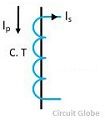 | 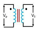 |
| Core | Usually built up with lamination of silicon steel. | It is made up of with high quality steel operating at low flux densities |
| Primary Winding | It carries the current which is to be measured | It carries the voltage which is to be measured. |
| Secondary Winding | It is connected to the current winding of the instrument. | It is connected to the meter or instrument. |
| Connection | Connected in series with the instrument | Connected in parallel with the instrument. |
| Primary Circuit | Has a small number of turns | Has a large number of turns |
| Secondary Circuit | Has a large number of turns and cannot be open circuit. | Has a small number of turns and can be open circuit. |
| Range | 5A or 1A | 110v |
| Transformation Ratio | High | Low |
| Burden | Does not depends on secondary burden | Depends on the secondary burden |
| Input | Constant current | Constant Voltage |
| Full line current | The primary winding consists the full line current. | The primary winding consists the full line voltage. |
| Types | Two types ( Wound and Closed Core ) | Two types (Electromagnetic and Capacitor voltage) |
| Impedance | Low | High |
| Applications | Measuring current and power, monitoring the power grid operation, for operating protective relay, | Measurement, power source, operating protective relay, |
Definition of Current Transformer
A current transformer is a device which is used for the transformation of current at a higher value to a lower value with respect to the earth potential. It is used with the AC instruments for measuring the high value of current.
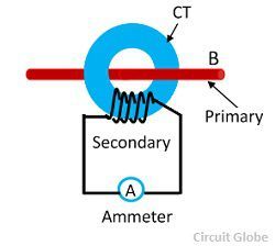 The line current is too high, and it is very difficult to measure them directly. Thus, the current transformer is used which decrease the high value of current into a fractional value which is easy to measure by the instrument.
The primary of the current transformer is connected directly to the line whose value is to measure.The secondary of the current transformer is connected to the ammeter or meter which measured the line value regarding fractions.
Definition of Potential Transformer
A voltage transformer is the type of instrument transformer which is used for the transformation of the voltage from a higher value to a lower value.
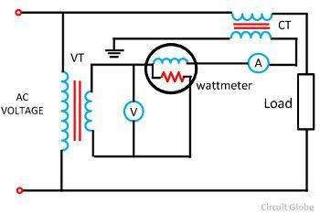 The primary terminal of the potential transformer is connected to the line for measuring the line voltage. The potential transformer reduced the high value of voltage into the small value which can easily be measured by the voltmeter or meter.
Key Differences between Current and Potential Transformer
- The current transformer transforms the high value of current into the low value so that it can conveniently measure by the instrument whereas the potential transformer converts the high value of voltage into low value.
- The primary winding of the current transformer is connected in series with the transmission line whose current is to be measured whereas the potential transformer is connected in parallel with the line.
- The core of the current transformer is built up with the laminations of the stainless steel. The core of the potential transformer is made up with high operating core operating at low flux densities.
- The primary winding of the current transformer carries the current which is to be measured whereas the primary of the potential transformer carries the voltage.
- The primary winding of the current transformers has a small number of turns, whereas in potential transformer the primary winding has a large number of turns.
- The secondary of the current transformer has a large number of turns, and it cannot be open circuited when it is under the services. The secondary winding of the potential transformer has a small number of turns, and it can be open circuit during the services.
- The normal range of the current transformer for measuring the current is 5A or 1A whereas the standard voltage at the secondary winding of the potential transformer is up to 110V.
- The transformation ratio of the current transformer is always remained high, whereas for the potential transformer its remains low.
- Note: The transformation ratio of the current and the voltage transformer is defined as the ratio of the rated primary voltage to the rated secondary voltage.
- The input of the current transformer is the constant current, whereas the input of the potential transformer is the constant voltage.
- The primary winding of the current transformer does not depend on the burden of the secondary winding of the transformer; it depends on the current flows in the primary windings whereas the primary of the potential transformer depends on the burden of the secondary winding.
- Note: Burden is the secondary load on the transformer.
- The primary winding of the current transformer is directly connected to the full line current whose current is to be measured whereas in potential transformer the full line voltage is directly connected to the primary terminal.
- The impedance of the primary winding of the transformer is very low as compared to the secondary winding whereas in a potential transformer, the impedance of the primary winding is high.
- Note: Impedance is the opposition of the current offered by the circuit when the voltage is applied across them.
- The current transformer is mainly used for measuring such magnitude of current that the meter or instrument cannot conveniently be measured whereas the potential transformer is used for measuring the high voltage of the current.
 For this product click on https://maatarinienterprises.in
Point to Remember: The current transformer is mainly used for relay protective scheme because it reduces the high magnitude of primary current to the suitable value for relay operation. The current transformer also provides insulation against the high voltage of the power circuit and hence protect the apparatus and personnel from high voltage.
Comments
Post a Comment
If any doubts let me know..